Tantalum electrolytic capacitors as discrete components are not ideal capacitors, as they have losses and parasitic inductive parts. All properties can be defined and specified by a series equivalent circuit composed of an idealized capacitance and additional electrical components which model all losses and inductive parameters of a capacitor. In this series-equivalent circuit the electrical characteristics are defined by:
[PDF Version]
Practical capacitors are available commercially in many different forms. The type of internal dielectric, the structure of the plates and the device packaging all strongly affect the characteristics of the capacitor, and its applications. Values available range from very low (picofarad range; while arbitrarily low values are in principle possible, stray (parasitic) capacitance in any circuit is the limiting factor) t.
[PDF Version]
Ideal capacitors and inductors can store energy indefinitely; however, in practice, discrete capacitors and inductors exhibit “leakage,” which typically results in a gradual reduction in the stored energy over time. . These two distinct energy storage mechanisms are represented in electric circuits by two ideal circuit elements: the ideal capacitor and the ideal inductor, which approximate the behavior of actual discrete capacitors and inductors. They also approximate the bulk properties of capacitance and. . Because capacitors and inductors can absorb and release energy, they can be useful in processing signals that vary in time. For example, they are invaluable in filtering and modifying signals with various time-dependent properties. But they cannot generate energy, so these are passive devices. Capacitors store. . This is a property of the configuration of the electrodes The unit C V-1 is called the FARAD (F). A capacitor is typically constructed as shown in Figure 5. When a voltage v is applied, the source deposits a. .
[PDF Version]
The electrical characteristics of capacitors are harmonized by the international generic specification IEC 60384-1. In this standard, the electrical characteristics of capacitors are described by an idealized series-equivalent circuit with electrical components which model all ohmic losses, capacitive and inductive parameters of an electrolytic capacitor:
[PDF Version]
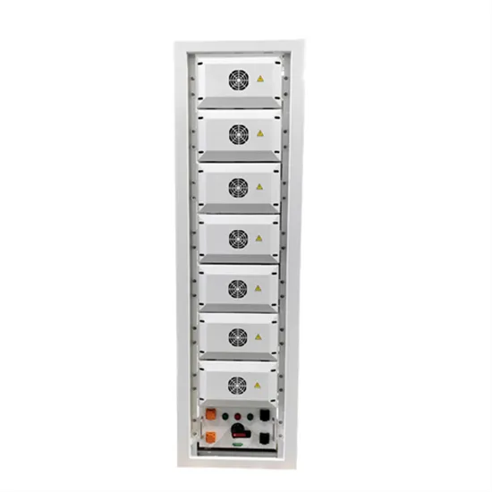
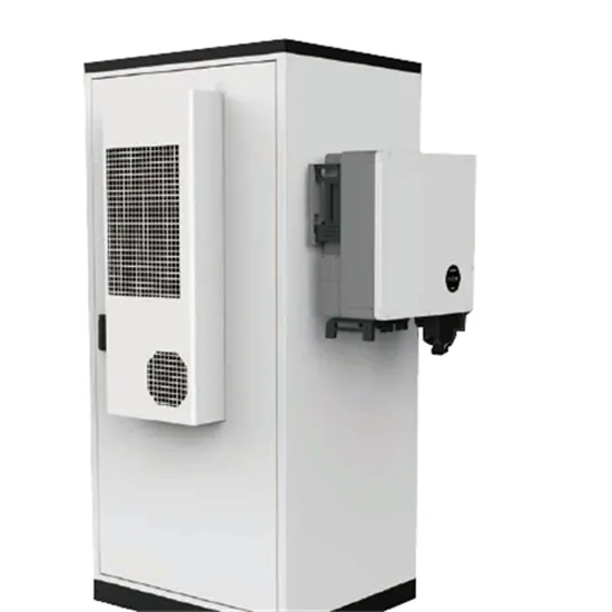
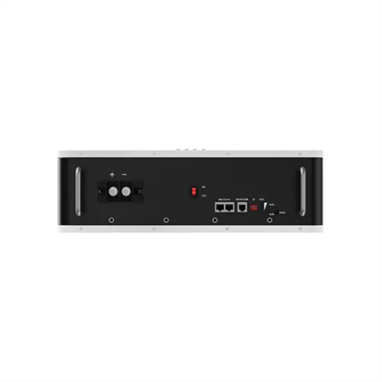
In this article, we'll explain the difference between DC-side and AC-side power, explore common battery ratios (0. 5P, 1P, 2P), and guide you on how to select the right ratio based on your application scenario. What is DC-Side Battery Ratio (P Rating)? The DC side refers to the battery side. . Energy storage systems are primarily categorized into three types: DC-side systems, AC-side systems, and load-side systems. Many buyers today are familiar with AC products, where a fully integrated solution is purchased from a single counterparty, typically an Original Equipment Manufacturer. . Choosing between direct current (DC) and alternating current (AC) for energy storage presents a big decision. Each system has its own characteristics that influence the choice, depending on specific needs and uses.
[PDF Version]
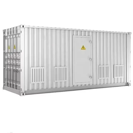
In this article, we outline the relative advantages and disadvantages of two common solar-plus-storage system architectures: ac-coupled and dc-coupled energy storage systems (ESS). . As mentioned above, PV modules will produce dc power. That power must be converted to ac to be used in most commercial and. . Retrofits Adding an ESS to an existing grid-tied interactive PV system is not uncommon. Doing so can cause headaches for system designers, and the easiest solution is often ac coupling the new ESS.. . DC-coupled systems rely only on a single multimode inverter that is fed by both the PV array and ESS. With this system architecture, dc output power from. . Efficiency While an ac-coupled system is more efficient when the PV array is feeding loads directly, a dc-coupled system is more efficient when power is routed through the ESS (e.g., when the.
[PDF Version]