The electrical characteristics of capacitors are harmonized by the international generic specification IEC 60384-1. In this standard, the electrical characteristics of capacitors are described by an idealized series-equivalent circuit with electrical components which model all ohmic losses, capacitive and inductive parameters of an electrolytic capacitor:
[PDF Version]
The vanadium redox battery (VRB), also known as the vanadium flow battery (VFB) or vanadium redox flow battery (VRFB), is a type of rechargeable which employs ions as . The battery uses vanadium's ability to exist in a solution in four different to make a battery with a single electroactive element instead of two.
[PDF Version]
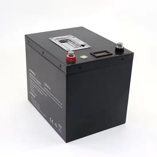
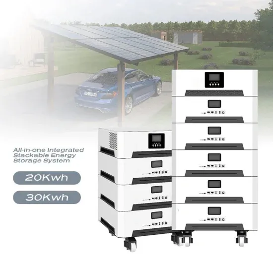
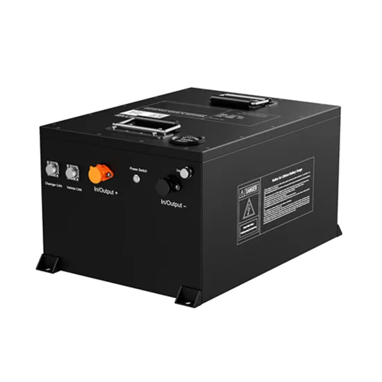
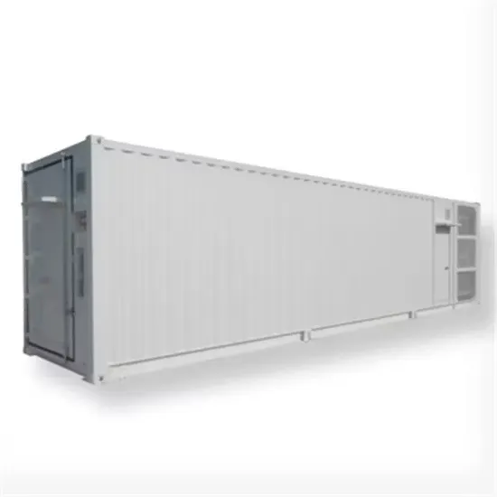
A BESS comprises several integral components, each crucial for maintaining efficiency and safety. The Image below demonstrates how these parts are connected in the BESS. . Battery Energy Storage System is a fundamental technology in the renewable energy industry. The system comprises a large enclosure housing multiple batteries designed to store electricity for later use. While various batteries can be utilized, the industry-standard uses. . Battery Energy Storage System plays an important role in the smart grid and the Internet of Things (IoT). 1. Power generation 2. Solar & wind farm 3. Virtual power plant for remote communities 4.. . Battery Energy Storage Systems are by far the most widely used subset of energy storage, and for good reason. They offer multiple advantages in. . The storage device is a Core component that stores energy charged from the grid or renewable sources. Below is the structure of our storage device with a breakdown of what each part does and how.
[PDF Version]
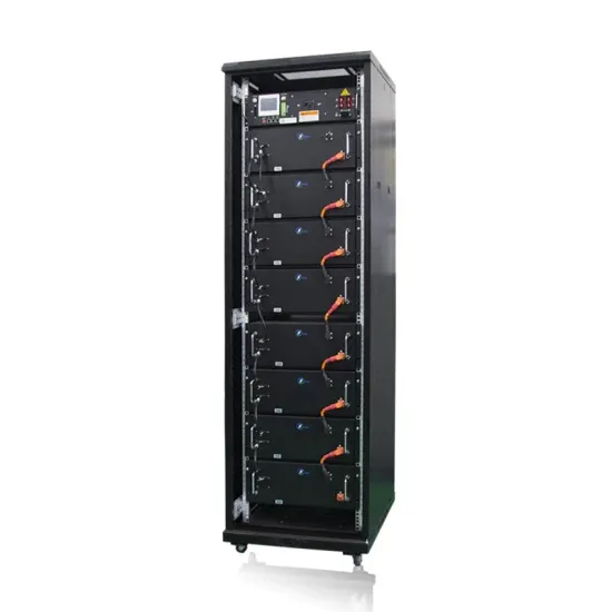
Fig. 1 below shows some typical nitrogen tanks. A liquid nitrogen tank, also known as a cryogenic tank or dewar, is a specialized container designed for the storage and transportation of liquid nitrogen. . Storing nitrogen serves several important purposes across various industries and applications. Here are some common reasons for the storage of nitrogen: Inerting: Nitrogen is an inert gas, meaning. . The main components of a liquid nitrogen tank include: 1. Inner Vessel:This is the innermost chamber that holds the liquid nitrogen. It is usually. . A liquid nitrogen tank, also known as a cryogenic tank or dewar, is a specialized container designed for the storage and transportation of liquid nitrogen. Unlike nitrogen gas stored in compressed gas cylinders, liquid nitrogen is extremely cold and maintained at a. . Nitrogen tanks come in various sizes and capacities to cater to different needs and applications. The size of a nitrogen tank is typically determined by its capacity to hold compressed nitrogen.
[PDF Version]
“ Use of phase change materials in wood and wood-based composites for thermal energy storage: A Review,” BioResources 18 (4), 8781-8805. These materials have a large capacity for storing. . To address the low efficiency and flammability of wood-based phase change materials (WPCMs) in solar energy storage, this study developed a series of WPCMs (PEG/TPP/DW-P) with both flame retardancy and solar-thermal energy storage properties by vacuum-impregnating polyethylene glycol (PEG). . Wood, a renewable and abundant biomass resource, holds substantial promise as an encapsulation matrix for thermal energy storage (TES) applications involving phase change materials (PCMs). However, practical implementations often reveal a disparity between observed and theoretical phase change. . Here we report on a wood-phase change material (PCM) composite, referred to as PCM-wood, which holds potential for energy-eficient buildings. The composite shows excellent thermal regulation capability with a melting enthalpy of 113 J g 1 at 22 ◦C and solidification enthalpy of 114 J g 1 at 21 ◦C.
[PDF Version]

First-generation flywheel energy-storage systems use a large steel flywheel rotating on mechanical bearings. Newer systems use carbon-fiber composite rotors that have a higher tensile strength than steel and can store much more energy for the same mass. . Flywheel energy storage (FES) works by spinning a rotor () and maintaining the energy in the system as . When energy is extracted from the system, the flywheel's rotational speed is reduced as a consequence of the. . A typical system consists of a flywheel supported by connected to a . The flywheel and sometimes. . TransportationAutomotiveIn the 1950s, flywheel-powered buses, known as . • • • – Form of power supply• – High-capacity electrochemical capacitor . GeneralCompared with other ways to store electricity, FES systems have long lifetimes (lasting decades with little or no. . Flywheels are not as adversely affected by temperature changes, can operate at a much wider temperature range, and are not subject to many of the common failures of chemical . They are also less potentially damaging to the environment, being largely made of . • Beacon Power Applies for DOE Grants to Fund up to 50% of Two 20 MW Energy Storage Plants, Sep. 1, 2009• Sheahen,.
[PDF Version]