! WARNING – Before installing product, read and understand all warnings, safety labels and instructions. Failure to do so could result in SERIOUS INJURY!. . ! WARNING: If the valve spool binds or will not rotate freely . Manufacturing Company, Inc. WARNING: Do not use these valves on applications where property damage or personal . “A” PORT TO CYLINDER “B” PORT TO CYLINDER “OUT” PORT TO FROM PUMP RESERVOIR TO “IN” PORT . 4-way control valve designed to operate a two-way hydraulic circuit from a single hydraulic source ! WARNING: If the valve will not hold in detent – discontinue use at once. Return valve for repair. Serious injury could result. ! WARNING: CONTAMINATION – Energy strongly.
[PDF Version]
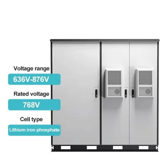
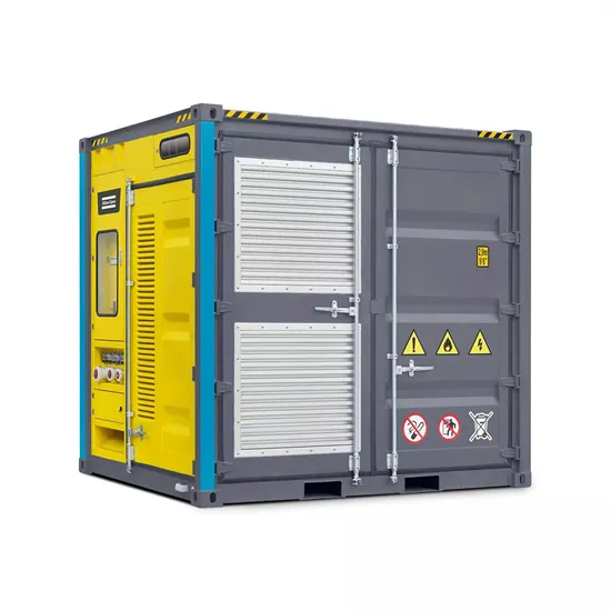
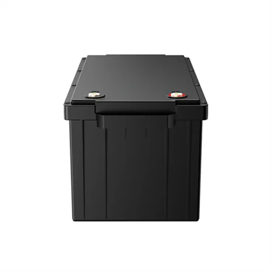
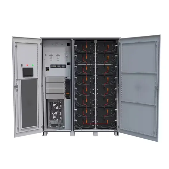
pioneered LFP along with SunFusion Energy Systems LiFePO4 Ultra-Safe ECHO 2.0 and Guardian E2.0 home or business energy storage batteries for reasons of cost and fire safety, although the market remains split among competing chemistries. Though lower energy density compared to other lithium chemistries adds mass and volume, both may be more tolerable in a static application. In 2021, there.
[PDF Version]
The basic working principle of a boiler is simple to understand. A boiler is a closed vessel where water is stored. Fuel, usually coal, is burned in a furnace to produce hot gases. The hot gases contact the water vessel, transferring their heat to the water, which produces steam in the boiler. Then this steam is piped to the turbine. . A boiler (also known as a steam boiler) is a closed vessel in which fluid (typically water) is heated. The fluid does not necessarily boil. The heated or vaporized fluid exits the boiler for use in various processes or heating applications, such as cooking, water or central heating, or boiler. . There are mainly two types of boiler – water tube boiler and fire tube boiler. In a fire tube boiler, hot gases pass through several tubes, which are surrounded. . Steam boiler efficiency is the percentage of total heat from the outlet steam compared to the total heat supplied by the fuel, usually coal. It includes with thermal efficiency, combustion efficiency and fuel to steam efficiency. Steam boiler efficiencydepends upon the size of boiler.
[PDF Version]
In this study, a model of the system was made in Matlab – Simulink for load-following, energy time-shifting, and photovoltaic power smoothing applications. . Determination of RTE of a storage system requires multidiscipline system modeling and simulations. The modeling and simulation presented in this paper determines the RTE of the flywheel storage system. Controlling the magnitude of phas currents regulates the rate o charge and discharge. The flywheel unit is fully compatible with the. .
[PDF Version]
The purpose of this study is to investigate potential solutions for the modelling and simulation of the energy storage system as a part of power system by comprehensively reviewing the state-of-the-art technology in energy storage system modelling methods and power system simulation methods. . Enhancing models to capture the value of energy storage in evolving power systems. Researchers at Argonne have developed several novel approaches to modeling energy storage resources in power system optimization and simulation tools including: By integrating these capabilities into our models and. . y storage in the power grid is pumped hydropower. But the storage technologies most frequently coupled with solar power plants are electrochemical storage (batteries) with PV plants and thermal storage (fluids) with CSP plants. With renewable energy adoption skyrocketing (pun intended), accurate modeling has become the Swiss Army knife for grid operators and energy innovators alike. This is where System Simulation comes into play.
[PDF Version]
The fundamental difference between conventional and flow batteries is that energy is stored in the electrode material in conventional batteries, while in flow batteries it is stored in the electrolyte. . A flow battery, or redox flow battery (after ), is a type of where is provided by two chemical components in liquids that are pumped through the system on. . A flow battery is a rechargeable in which an containing one or more dissolved electroactive elements flows through an . The cell uses redox-active species in fluid (liquid or gas) media. Redox flow batteries are rechargeable () cells. Because they employ rather than or they are more similar to fuel cells than to conventional. . Compared to inorganic redox flow batteries, such as vanadium and Zn-Br2 batteries, organic redox flow batteries' advantage is the tunable redox properties of their active components. As of. . The (Zn–Br2) was the original flow battery. John Doyle file patent on September 29, 1879. Zn-Br2 batteries have relatively high specific energy, and were demonstrated. . Redox flow batteries, and to a lesser extent hybrid flow batteries, have the advantages of:• Independent scaling of energy (tanks) and power (stack), which allows for a cost/weight/etc.. . The hybrid flow battery (HFB) uses one or more electroactive components deposited as a solid layer. The major disadvantage is that this reduces decoupled.
[PDF Version]