In this study, a model of the system was made in Matlab – Simulink for load-following, energy time-shifting, and photovoltaic power smoothing applications. . Determination of RTE of a storage system requires multidiscipline system modeling and simulations. The modeling and simulation presented in this paper determines the RTE of the flywheel storage system. Controlling the magnitude of phas currents regulates the rate o charge and discharge. The flywheel unit is fully compatible with the. .
[PDF Version]

A typical 1 MW flywheel system ranges between $300,000 to $600,000. But why the gap? It's like comparing a bicycle to a Ferrari – both have wheels, but the specs matter. Rotor material: Carbon fiber? Steel? Your choice adds $100k+ swings. Vacuum systems: Better seals = less friction =. . The cost of a flywheel energy storage system varies based on several factors, including size, design, and installation requirements. The largest flywheel energy storage is in New York,USA by Beacon Power with a power rat. . As global industries seek cost-effective energy storage, flywheel systems emerge as game-changers with flywheel energy storage cost per kWh dropping 28% since 2020. Unlike lithium-ion batteries requiring frequent replacements, a California data center using 10MW flywheel array achieved $1,200/kWh. . RotorVault's storage product for data center applications is the most cost-competitive solution offering both backup power for critical IT and active power conditioning. When technologies like lithium batteries are used for power conditioning, they drive high operations and maintenance costs.
[PDF Version]
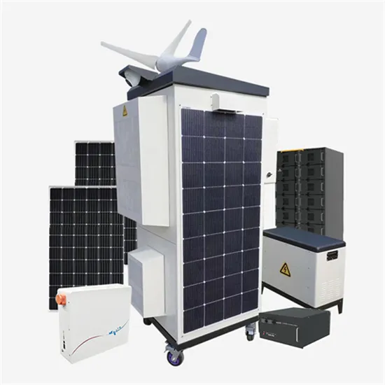
A typical system consists of a flywheel supported by connected to a . The flywheel and sometimes motor–generator may be enclosed in a to reduce friction and energy loss. First-generation flywheel energy-storage systems use a large flywheel rotating on mechanical bearings. Newer systems use composite that have a hi.
[PDF Version]
First-generation flywheel energy-storage systems use a large steel flywheel rotating on mechanical bearings. Newer systems use carbon-fiber composite rotors that have a higher tensile strength than steel and can store much more energy for the same mass. . Flywheel energy storage (FES) works by spinning a rotor () and maintaining the energy in the system as . When energy is extracted from the system, the flywheel's rotational speed is reduced as a consequence of the. . A typical system consists of a flywheel supported by connected to a . The flywheel and sometimes. . TransportationAutomotiveIn the 1950s, flywheel-powered buses, known as . • • • – Form of power supply• – High-capacity electrochemical capacitor . GeneralCompared with other ways to store electricity, FES systems have long lifetimes (lasting decades with little or no. . Flywheels are not as adversely affected by temperature changes, can operate at a much wider temperature range, and are not subject to many of the common failures of chemical . They are also less potentially damaging to the environment, being largely made of . • Beacon Power Applies for DOE Grants to Fund up to 50% of Two 20 MW Energy Storage Plants, Sep. 1, 2009• Sheahen,.
[PDF Version]
A typical system consists of a flywheel supported by connected to a . The flywheel and sometimes motor–generator may be enclosed in a to reduce friction and energy loss. First-generation flywheel energy-storage systems use a large flywheel rotating on mechanical bearings. Newer systems use composite that have a hi.
[PDF Version]
In the 1950s, flywheel-powered buses, known as, were used in () and () and there is ongoing research to make flywheel systems that are smaller, lighter, cheaper and have a greater capacity. It is hoped that flywheel systems can replace conventional chemical batteries for mobile applications, such as for electric vehicles. Proposed flywheel systems would eliminate many of th.
[PDF Version]