Fig. 1 below shows some typical nitrogen tanks. A liquid nitrogen tank, also known as a cryogenic tank or dewar, is a specialized container designed for the storage and transportation of liquid nitrogen. . Storing nitrogen serves several important purposes across various industries and applications. Here are some common reasons for the storage of nitrogen: Inerting: Nitrogen is an inert gas, meaning. . The main components of a liquid nitrogen tank include: 1. Inner Vessel:This is the innermost chamber that holds the liquid nitrogen. It is usually. . A liquid nitrogen tank, also known as a cryogenic tank or dewar, is a specialized container designed for the storage and transportation of liquid nitrogen. Unlike nitrogen gas stored in compressed gas cylinders, liquid nitrogen is extremely cold and maintained at a. . Nitrogen tanks come in various sizes and capacities to cater to different needs and applications. The size of a nitrogen tank is typically determined by its capacity to hold compressed nitrogen.
[PDF Version]
The vanadium redox battery (VRB), also known as the vanadium flow battery (VFB) or vanadium redox flow battery (VRFB), is a type of rechargeable which employs ions as . The battery uses vanadium's ability to exist in a solution in four different to make a battery with a single electroactive element instead of two.
[PDF Version]
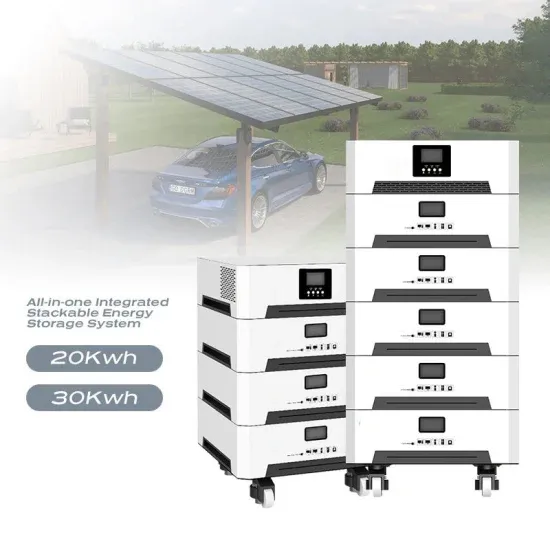
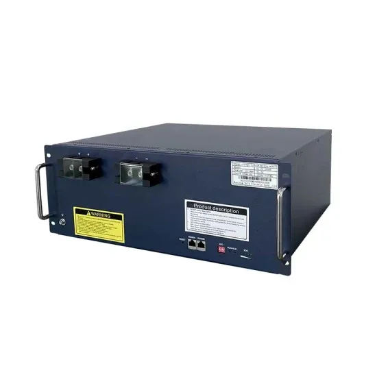
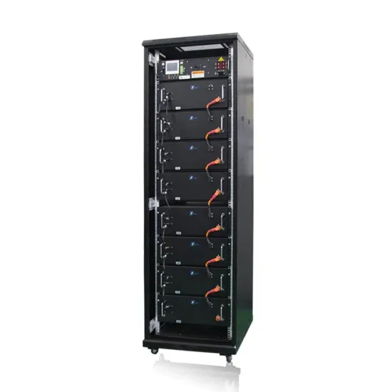
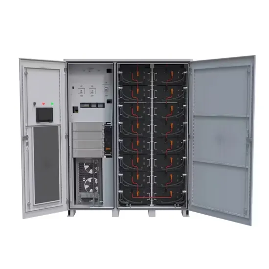
A battery energy storage system (BESS), battery storage power station, battery energy grid storage (BEGS) or battery grid storage is a type of technology that uses a group of in the grid to store . Battery storage is the fastest responding on, and it is used to stabilise those grids, as battery storage can transition from standby to full power in u.
[PDF Version]
The fundamental difference between conventional and flow batteries is that energy is stored in the electrode material in conventional batteries, while in flow batteries it is stored in the electrolyte. . A flow battery, or redox flow battery (after ), is a type of where is provided by two chemical components in liquids that are pumped through the system on. . A flow battery is a rechargeable in which an containing one or more dissolved electroactive elements flows through an . The cell uses redox-active species in fluid (liquid or gas) media. Redox flow batteries are rechargeable () cells. Because they employ rather than or they are more similar to fuel cells than to conventional. . Compared to inorganic redox flow batteries, such as vanadium and Zn-Br2 batteries, organic redox flow batteries' advantage is the tunable redox properties of their active components. As of. . The (Zn–Br2) was the original flow battery. John Doyle file patent on September 29, 1879. Zn-Br2 batteries have relatively high specific energy, and were demonstrated. . Redox flow batteries, and to a lesser extent hybrid flow batteries, have the advantages of:• Independent scaling of energy (tanks) and power (stack), which allows for a cost/weight/etc.. . The hybrid flow battery (HFB) uses one or more electroactive components deposited as a solid layer. The major disadvantage is that this reduces decoupled.
[PDF Version]
Electricity can be stored directly for a short time in capacitors, somewhat longer electrochemically in, and much longer chemically (e.g. hydrogen), mechanically (e.g. pumped hydropower) or as heat. The first pumped hydroelectricity was constructed at the end of the 19th century around in Italy, Austria, and Switzerland. The technique rapidly expanded during the 1960s to 1980s,.
[PDF Version]